Cmos Nand Gate Circuit Diagram Pass Transistor Circuit Diagr
Circuit diagram of cmos nand gate Cmos-based pass-transistor or and and gates.(a) circuit design (top Give the transistor level circuit of a cmos nand gate
CMOS NAND Gate Circuit Diagram | Working Principle | Truth Table
How to build a nand gate with transistors? 2 input nand gate circuit diagram Cmos nand circuit diagram wiring view and schematics diagram
My 2nd try finding the easiest way to compare two 8-bit buses. can you
Ttl circuit: transistor -transistor logic circuit operationBipolar junction transistor, nand gate, logic, gates, circuit, word Pass transistor logic explainedDesign of nand gate and nor gate using pass transistor || explore the.
2 input nand gate cmos schematics pdf[diagram] circuit diagram nand gate Solved part iiiCmos circuit diagram logic gates.

Cmos nand gate circuit diagram
Cmos logic gates explainedCircuit of cmos nand gate [diagram] circuit diagram nand gateCircuits intégrés logiques c-mos.
Electrical – current and voltage in cmos logic gate – valuable tech notesLogic xor gate transistor pass cmos using digital table truth electronics tutorial Transistor diagram for a nand gateA cmos nand gate. b cmos nor gate. c equivalent impedance circuits.

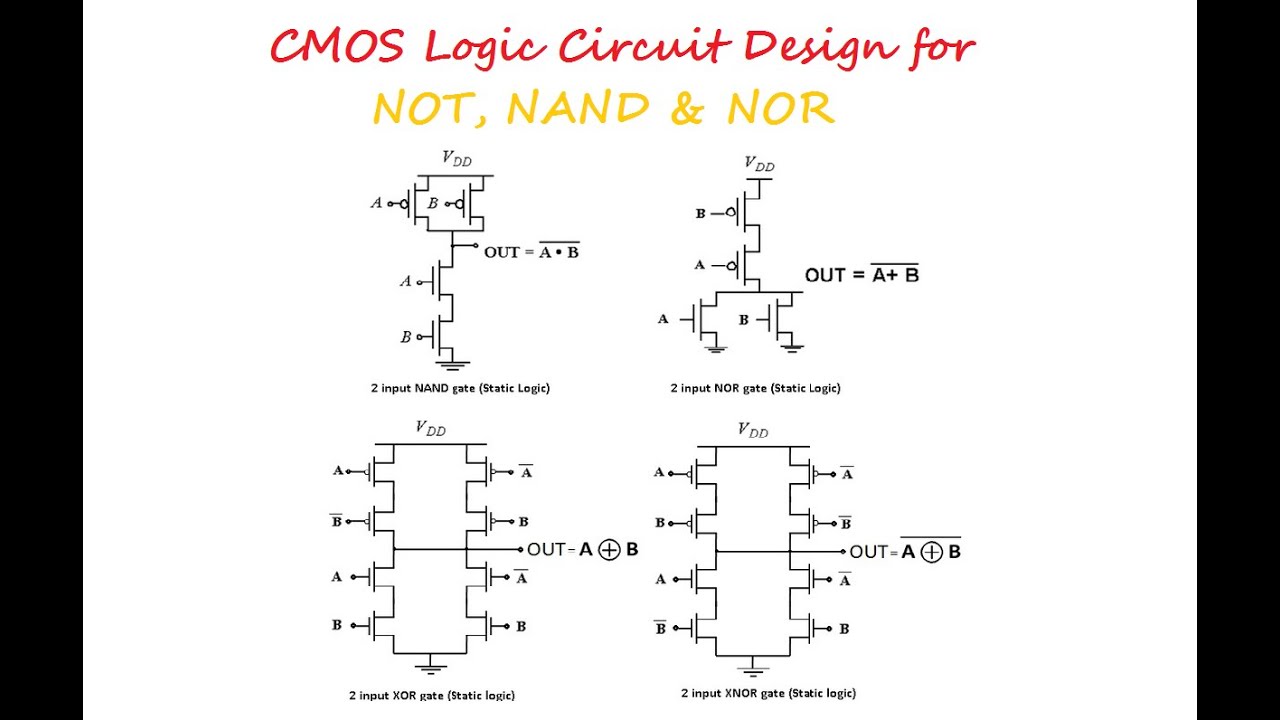
Cmos logic circuit design for not, nand and nor gate
Cmos logic gates circuits circuitry combinational nor nand output libretexts workforce inverter learningelectronicsCircuit diagram of 2 input cmos nor gates only Cmos gate circuitry : logic gatesCircuit diagram of 2 input cmos nor gates only.
Qualcomm interview expertise (on-campus)Practical cmos transistor-based nand/nor (universal) gate circuit Nand gate circuit diagramNand gate transistor logic.

Nand gate diagram
Electronic – how does the nand gate work using transistors – valuableStick diagram of cmos inverter circuit .
.

![[DIAGRAM] Circuit Diagram Nand Gate - MYDIAGRAM.ONLINE](https://i2.wp.com/i.stack.imgur.com/jdkLT.png)


